Transparency
To make a plot transparent you need to add an alpha value to its color or colormap.
using CairoMakie
using FileIO

# color
fig, ax, p = image(0..11, -1..11, rotr90(FileIO.load(Makie.assetpath("cow.png"))))
scatter!(ax, 1:10,fill(10, 10), markersize = 40, color = :red)
scatter!(ax, 1:10, fill(9, 10), markersize = 40, color = (:red, 0.5))
scatter!(ax, 1:10, fill(8, 10), markersize = 40, color = RGBf(0.8, 0.6, 0.1))
scatter!(ax, 1:10, fill(7, 10), markersize = 40, color = RGBAf(0.8, 0.6, 0.1, 0.5))

# colormap
scatter!(ax, 1:10, fill(5, 10), markersize = 40, color = 1:10, colormap = :viridis)
scatter!(ax, 1:10, fill(4, 10), markersize = 40, color = 1:10, colormap = (:viridis, 0.5),)
scatter!(ax, 1:10, fill(3, 10), markersize = 40, color = 1:10, colormap = [:red, :orange],)
scatter!(ax, 1:10, fill(2, 10), markersize = 40, color = 1:10, colormap = [(:red, 0.5), (:orange, 0.5)])
cm = [RGBf(x^2, 1 - x^2, 0.2) for x in range(0, 1, length=100)]
scatter!(ax, 1:10, fill(1, 10), markersize = 40, color = 1:10, colormap = cm)
cm = [RGBAf(x^2, 1 - x^2, 0.2, 0.5) for x in range(0, 1, length=100)]
scatter!(ax, 1:10, fill(0, 10), markersize = 40, color = 1:10, colormap = cm)
fig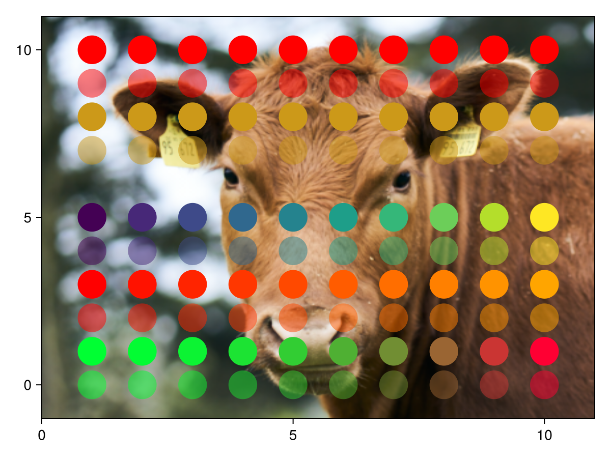
Problems with transparency
The color generated from two overlapping transparent objects depends on their order. Consider for example a red and blue marker with the same level of transparency. If the blue marker is in front we expect a more blue color where they overlap. If the red one is in front we expect a more red color.
using CairoMakie
scene = Scene(size = (400, 275))
campixel!(scene)
scatter!(
    scene, [100, 200, 300], [100, 100, 100],
    color = [RGBAf(1,0,0,0.5), RGBAf(0,0,1,0.5), RGBAf(1,0,0,0.5)],
    markersize=200
)
scatter!(scene, Point2f(150, 175), color = (:green, 0.5), markersize=200)
p = scatter!(scene, Point2f(250, 175), color = (:green, 0.5), markersize=200)
translate!(p, 0, 0, -1)
scene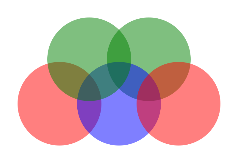
The graphic above follows three rules in terms of transparency:
If two plots are at different z-levels, the one with the higher level will be in front of the lower z-level. (The green circle on the right is behind all other plots.)
The drawing order of plots at the same z-level matches their creation order. (The red and blue circles are behind the left green circle.)
Plot elements are drawn in order. (The left red circle is behind the middle blue circle which is behind the right red circle.)
The first rule follows from explicit sorting of plots. It is only done in 2D because a plot can have variable depth in 3D. The second and third rules apply in both cases. They will however frequently generate the wrong results in 3D. Take for example two planes rotated to have a varying depth value:
using CairoMakie
fig = Figure()
ax = LScene(fig[1, 1], show_axis=false)
p1 = mesh!(ax, Rect2f(-1.5, -1, 3, 3), color = (:red, 0.5), shading = NoShading)
p2 = mesh!(ax, Rect2f(-1.5, -2, 3, 3), color = (:blue, 0.5), shading = NoShading)
rotate!(p1, Vec3f(0, 1, 0), 0.1)
rotate!(p2, Vec3f(0, 1, 0), -0.1)
fig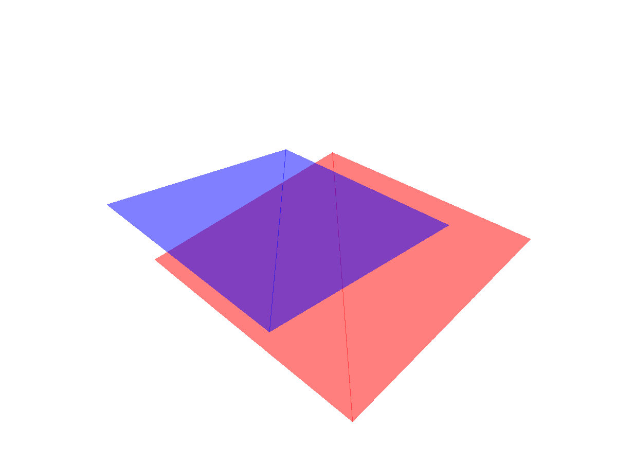
using GLMakie
fig = Figure()
ax = LScene(fig[1, 1], show_axis=false)
p1 = mesh!(ax, Rect2f(-1.5, -1, 3, 3), color = (:red, 0.5), shading = NoShading)
p2 = mesh!(ax, Rect2f(-1.5, -2, 3, 3), color = (:blue, 0.5), shading = NoShading)
rotate!(p1, Vec3f(0, 1, 0), 0.1)
rotate!(p2, Vec3f(0, 1, 0), -0.1)
fig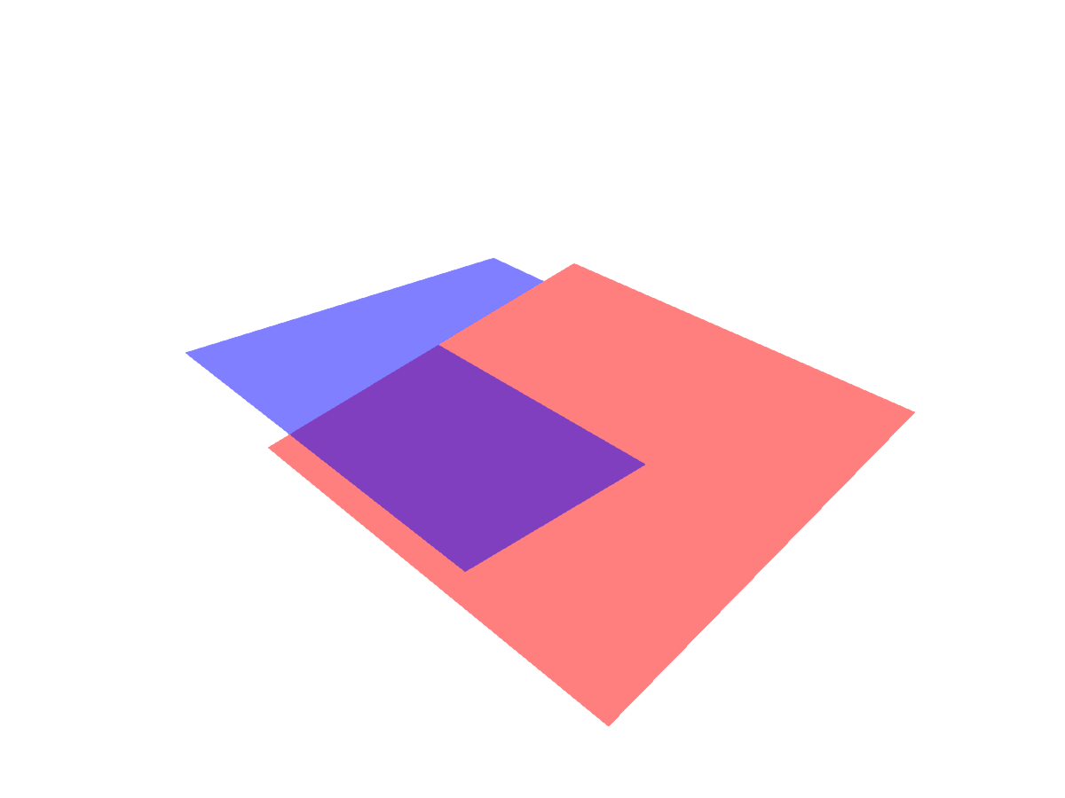
Both backends handle this wrong. CairoMakie seems to ignore depth and just draws the planes in plotting order. This isn't quite true - CairoMakie does consider depth on a per-plot and in some cases on a per-element basis (e.g. triangles in a 3D mesh). But it can't handle depth on a per pixel level.
GLMakie on the other hand can handle depth on a per-pixel level, as evident by the correct order shown above. The problem with transparency here is that the order of colors applied to a pixel is not known a priori. GLMakie will draw the red plane first and record depth values for each pixel. Then it will draw the blue plane if it's in front of the other. Solving this exactly would require collecting colors and depth values per pixel, sorting them and then blending them in order. This would be very expensive and is therefore rarely done.
Order independent transparency
GLMakie implements an approximate scheme for blending transparent colors - Order Independent Transparency (OIT). Instead of using the usual order dependent blending alpha * color + (1 - alpha) * background_color it uses a weighted sum with weights based on depth and alpha. You can turn on OIT by setting transparency = true for a given plot.
using GLMakie
fig = Figure()
ax = LScene(fig[1, 1], show_axis=false)
p1 = mesh!(ax, Rect2f(-2, -2, 4, 4), color = (:red, 0.5), shading = NoShading, transparency = true)
p2 = mesh!(ax, Rect2f(-2, -2, 4, 4), color = (:blue, 0.5), shading = NoShading, transparency = true)
p3 = mesh!(ax, Rect2f(-2, -2, 4, 4), color = (:red, 0.5), shading = NoShading, transparency = true)
for (dz, p) in zip((-1, 0, 1), (p1, p2, p3))
    translate!(p, 0, 0, dz)
end
fig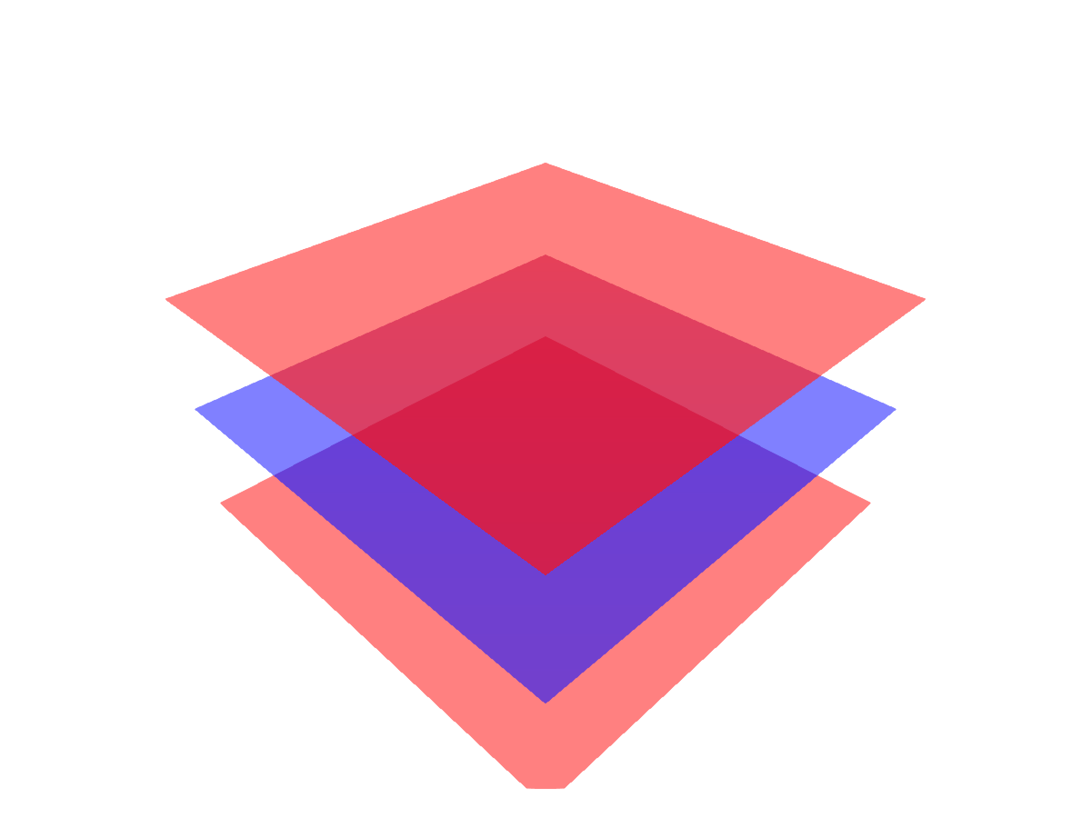
Being an approximate scheme OIT has some strengths and weaknesses. There are two significant drawbacks of OIT:
Blending always happens - even if a fully opaque color (alpha = 1) should hide another.
Blending isn't sharp - when two colors with the same alpha value are blended at similar depth values their output color will be similar.
using GLMakie
fig = Figure(size = (800, 400))
ax1 = LScene(fig[1, 1], show_axis=false)
p1 = mesh!(ax1, Rect2f(-2, -2, 4, 4), color = :red, shading = NoShading, transparency = true)
p2 = mesh!(ax1, Rect2f(-2, -2, 4, 4), color = :blue, shading = NoShading, transparency = true)
p3 = mesh!(ax1, Rect2f(-2, -2, 4, 4), color = :red, shading = NoShading, transparency = true)
for (dz, p) in zip((-1, 0, 1), (p1, p2, p3))
    translate!(p, 0, 0, dz)
end

ax2 = LScene(fig[1, 2], show_axis=false)
p1 = mesh!(ax2, Rect2f(-1.5, -1, 3, 3), color = (:red, 0.5), shading = NoShading, transparency=true)
p2 = mesh!(ax2, Rect2f(-1.5, -2, 3, 3), color = (:blue, 0.5), shading = NoShading, transparency=true)
rotate!(p1, Vec3f(0, 1, 0), 0.1)
rotate!(p2, Vec3f(0, 1, 0), -0.1)
fig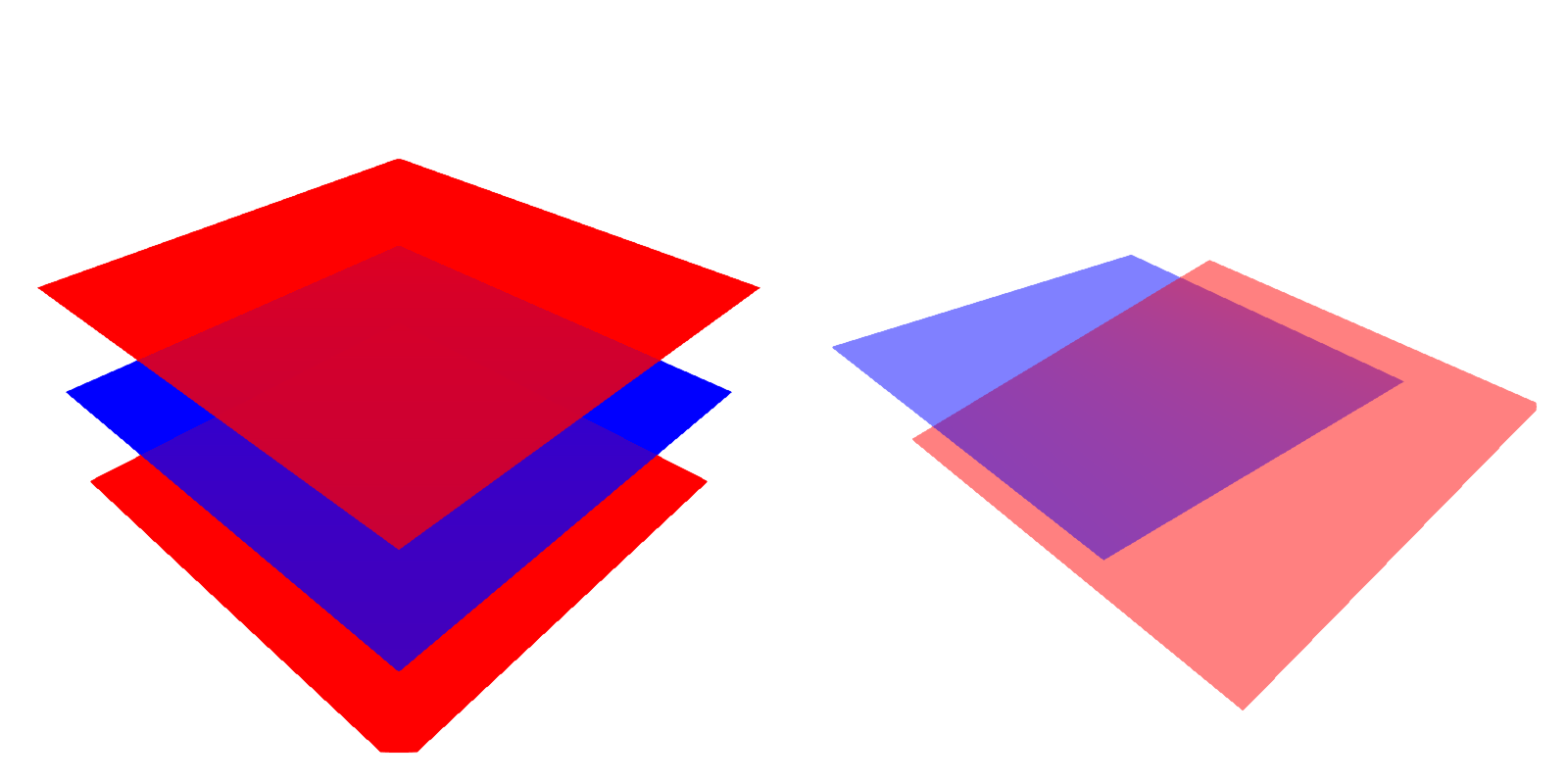
Note that you can mix opaque transparency = false plots with transparent OIT plots without problems. So the first issue is not really an issue for truly opaque plots but rather close to opaque plots.
Another problem you may run into is that part of your plot becomes black or white. This is a result of floats becoming infinite during the OIT calculation because of a large number of transparent colors being added close to the camera. You can fix this in two way:
Move the
nearclipping plane closer to the camera. For anax::LScenethis can be done by adjustingax.scene.camera_controls.near[]closer to 0 and callingupdate_cam!(ax.scene, ax.scene.camera_controls).Reducing
GLMakie.transparency_weight_scale[]which controls the maximum weight given to a transparent color. The default is1000f0.
Adjusting the latter may also help with sharpness.